RB900L3 Connectors: Różnice pomiędzy wersjami
Znaczniki: Ręczne wycofanie zmian Wycofane |
|||
| (Nie pokazano 18 pośrednich wersji utworzonych przez tego samego użytkownika) | |||
| Linia 1: | Linia 1: | ||
{{Template: Connectors | {{Template: Connectors | ||
| model = RB900L3 | | model = RB900L3 | ||
| type = modem | | type = modem | ||
| psr = 5..30 V DC, 2.5 W max. continuous power | |||
| sim = 1 | |||
}} | }} | ||
Aktualna wersja na dzień 15:55, 10 maj 2023
This page contains connectors description of RB900L3 modem.
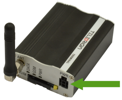
Power supply connector
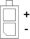
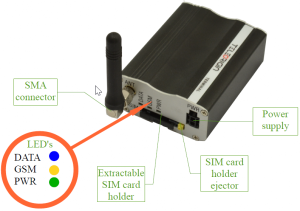
Please use power adapter which is included in package. It ensures “clean” power supply input and avoids short transients on power supply lines originating from inductive load switching. The power supply connector is a 2-pin connector for external DC power supply. Power supply range of RB900L3 is 5..30 V DC, 2.5 W max. continuous power.
| Pin | Name | Direction | Description |
|---|---|---|---|
| + | V+ | IN | 5..30 V DC, 2.5 W max. continuous power |
| - | GND | - | Ground |
NOTE: The device is switched off by removing the external power supply from the electric socket. The electric socket must be located close to the device and easily accessible.
Main SIM card holder
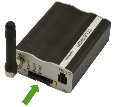
External, main SIM card holder is placed at the front of the RB900L3 modem (as shown below). To insert a SIM card into the holder, press the yellow button, eject the black drawer, place the SIM card inside it and insert drawer into the modem (you will hear "click"). To operate the module in a GSM/LTE network, it is necessary to insert active SIM card from the network provider.
Antenna connectors
GSM antenna connector
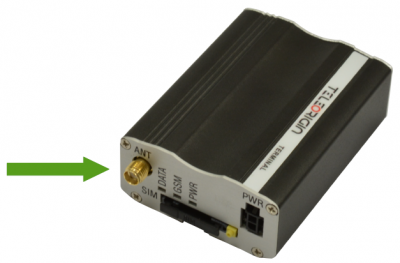
SMA “ANT” input is used to connect external GSM/LTE antenna. To establish a connection with a GSM/LTE network, an external antenna must be used. Type of antenna depends of GSM/LTE coverage. In good circumstances (level of received signal is high) use antenna contained in the package. If the range of GSM/LTE is low or none, an outdoor or indoor (for instance in place where GSM/LTE range is sufficient) antenna should be used.
Note: If there is no antenna connected to SMA connector, the connection with GSM/LTE network is impossible.
GPS/GNSS antenna connector
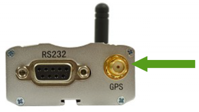
An SMA "GNSS" input is used to connect an external GNSS antenna. To establish connection with GPS/GNSS sattelites and check the coordinates of the device, an external antenna must be used and should be located outdoors.
Interfaces
Front
Back
USB
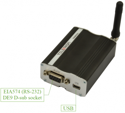
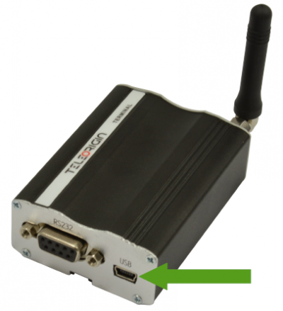
RB900L3 modem is equipped with a USB interface (as shown below) – miniUSB connector.
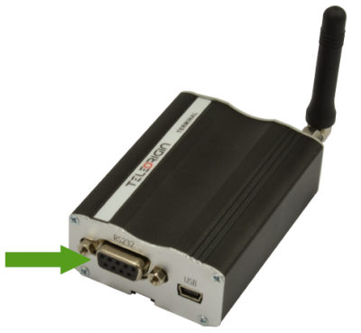
RS232
RB900L3 modem is equipped with an RS232 interface (as shown below). The DE9 DSUB socket is connected via a voltage level translator circuit to the GSM/LTE module.
Table of RS232 pins (DCE female connector):
| Pin | Name | Direction | Description |
|---|---|---|---|
| 1 | DCD | OUT | Data Carrier Detect |
| 2 | RXD | OUT | Receive Data (a.k.a Rx, RD) |
| 3 | TXD | IN | Transmit Data (a.k.a Tx, TD) |
| 4 | DTR | IN | Data Terminal Ready |
| 5 | GND | - | Ground |
| 6 | DSR | OUT | Data Set Ready |
| 7 | RTS | IN | Request To Send |
| 8 | CTS | OUT | Clear To Send |
| 9 | RI | OUT | Ring Indicator |
