NTS-pico3 Connectors: Różnice pomiędzy wersjami
Znacznik: Wycofane |
Znacznik: Ręczne wycofanie zmian |
||
| (Nie pokazano 5 pośrednich wersji utworzonych przez tego samego użytkownika) | |||
| Linia 1: | Linia 1: | ||
{{Template: | {{Template: Connectors | ||
| model = NTS-pico3 | | model = NTS-pico3 | ||
| type = time server | | type = time server | ||
| psr = 9..30 V DC, typical: 1.2-1.6W, max. typical: <2W (peak when active GNSS antenna is not shorted and USB not connected), max. possible: <8W (info for safety, when short-circuit on internal 5V) | | psr = 9..30 V DC, typical: 1.2-1.6W, max. typical: <2W (peak when active GNSS antenna is not shorted and USB not connected), max. possible: <8W (info for safety, when short-circuit on internal 5V) | ||
| ip_address_link = | | ip_address_link = [[NTS-pico3_Local_network]] | ||
}} | }} | ||
Aktualna wersja na dzień 09:42, 2 sie 2023
This page contains connectors description of NTS-pico3 time server.
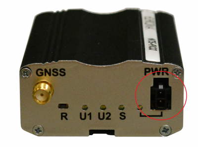
Power supply connector
Please use power adapter which is included in package. It ensures “clean” power supply input and avoids short transients on power supply lines originating from inductive load switching. The power supply connector is a 2-pin connector for external DC power supply. Power supply range of NTS-pico3 is 9..30 V DC, typical: 1.2-1.6W, max. typical: <2W (peak when active GNSS antenna is not shorted and USB not connected), max. possible: <8W (info for safety, when short-circuit on internal 5V).
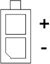
| Pin | Name | Direction | Description |
|---|---|---|---|
| + | V+ | IN | 9..30 V DC, typical: 1.2-1.6W, max. typical: <2W (peak when active GNSS antenna is not shorted and USB not connected), max. possible: <8W (info for safety, when short-circuit on internal 5V) |
| - | GND | - | Ground |
NOTE: The device is switched off by removing the external power supply from the electric socket. The electric socket must be located close to the device and easily accessible.
Antenna connectors
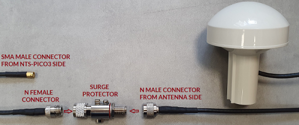
Connect the antenna and surge arrestor as shown in the picture below.
NTS-Pico3 antenna specification:
| Parameter | Value |
|---|---|
| Frequency | 1575.42 MHz |
| Impedance | 50 Ω |
| V.S.W.R | <2.0 Max |
| Gain | 38 dB |
| Power supply | 3-5VDC (10 mA) |
| Noise fig. | <1.5 dB Typ. |
| Polarisation | RHC (Right Hand Circular) |
| Antenna type | Active GPS |
| Cable cover | black |
| Antenna cable | 30m H155 |
| Connector type | SMA m |
Interfaces
Serial ports
Serial RS232 and RS485 port (RJ-45 connector marked as “RS232/485”) is placed on front panel of time server. Pinout is described in the table below:
| RS232/RS485 signal | RJ45 connector |
|---|---|
| A | 1 |
| 5V | 2 |
| B | 3 |
| GND | 4 |
| TX | 5 |
| RX | 6 |
| RTS | 7 |
| CTS | 8 |
LAN connector
Second RJ-45 connector (marked as "LAN") is placed next to serial connector and is used for communication with PC or laptop through Ethernet interface. WWW configuration is available in the web browser (default IP address is 192.168.1.234). You can change the default IP address in NTS-pico3_Local_network.
WARNING: Do not connect the PoE (Power-over-Ethernet) connection to the LAN port. Otherwise it may damage the device!
"R" button - factory reset
To reset the time server to the factory default configuration push the "R" button for at least 5 seconds, then release it and wait for system boot.
TR switch
TR switch is is used to add the termination resistance for RS485 interface.


